- PCB Engineering
- CAM Procedures
- Gerber File
- Gerber Generation
- Pick&Place Generation
- DFM Check Item
- DFM Check Details
- PCB FAB Tutorial
- Finished Surface
- Impedance Apply
- Impedance Type
- PCB Laminates|Stackup
- Stackup with Impedance
- Capabilities
- Tolerances
- Material Comparison Chart
- Rogers Matierl datasheets
- Rogers Material Choose
- Avoid missing Feature
- HDI PCB Stackup
Gerber File Generation
In the PCB design layout industry, there are so many EDA software to make the PCB layout, now we list the main
and popular software for your reference:
l Cadence Allegro
l Eagle
l Altium
l Mentor Graphics -PADS
Now let us talk about the fabrication file generation:
Cadence (Allegro)
To generate the Gerber file , open your PCB layout in Allegro and click Manufacture>>Artwork . Then Artwork
Control Form will be seen.
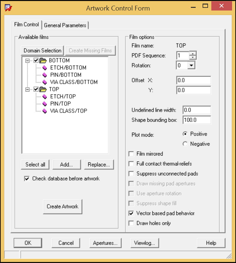
Then it's time to add a board
outline by right-clicking on the TOP folder and picking Add Manual.
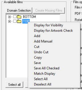
Determine a film name, OUTLINE for example and click OK.

In the Subclass Selection window, expand BOARD GEOMETRY and tick in front of OUTLINE. Then,
click OK button.
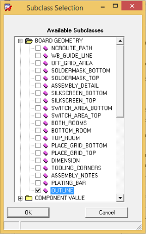
Back to Artwork Control Form window, tick in front of OUTLINE if it has stayed in the area of
Available films.
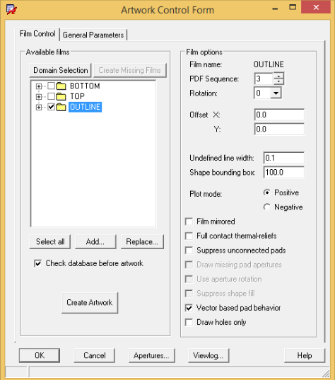
With those steps finished, press Select all button with all the layers output. Then, Gerber files will be
generated when Create Artwork button is clicked.
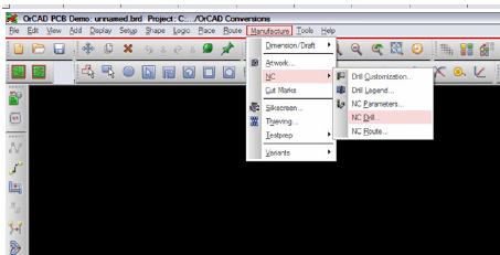
To generate the NC Drill file, go back to Manufacture > NC > NC Drill
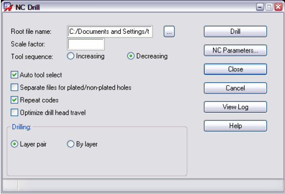
The NC Drill dialog box will open. Confirm that Root file name is present (board name.drl) and select Auto Tool
Select. Click on the Drill button to generate the NC Drill file
Eagle
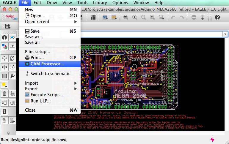
Open your PCB layout with EAGLE software and click File>>CAM Processor. Then you'll encounter a popup
dialog.
In this dialog window, click File>>Open>>Job and open a design file in a new window that is shown
below.
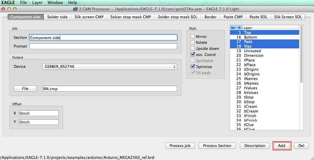
In this window, you should define Gerber files in terms of Component side, Solder side, Silk screen CMP, Solder
stop mask CMP, Solder stop mask SOL, Border, Paste CMP, Paste SOL and Silk Screen SOL. As soon as all
parameters under all buttons in this window have been determined, you can generate Gerber files by clicking
Process Job button.
Altium
With your .pcb file opened with Altium Designer software, click File>>Fabrication Outputs>>Gerber
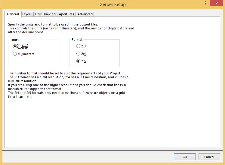
Files sequently. Then, Gerber Setup dialogue window will come out, in which five items are available for engineers
to set corresponding parameters in their Gerber files: General, Layers, Drilling Drawing, Apertures and Advanced.
• General button
Under General button, two parameters should be determined: Units and Format. For Units, either Inches or
Millimeters can be selected. For Format, three alternatives are supplied. The highest resolution is 2:5 whereas the
lowest resolution is 2:3.
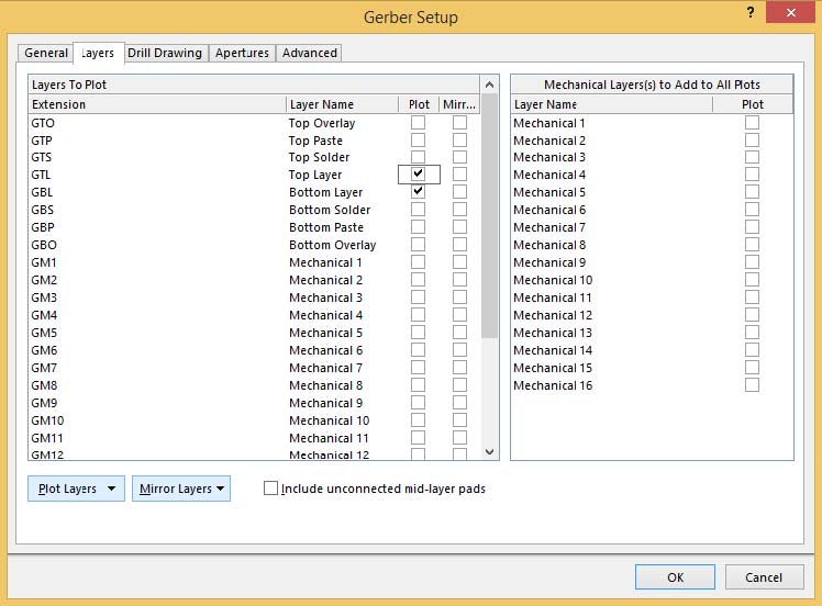
Layers
In this tab, layers to plot and to mirror should be determined. Cross can be marked at the end of layers that need
to be plotted or mirrored. Mechanical
layers to add to all plots can be neglected.
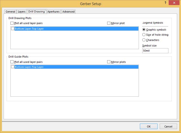
Drill Drawing
Little should be done in this tab and Legend symbols don't matter much.
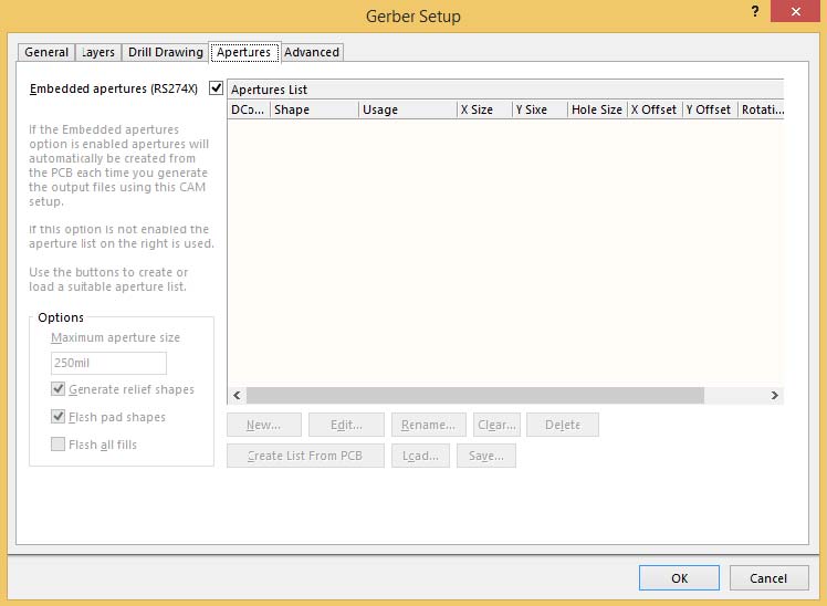
Apertures
Based on the discussion talked about previously in this article, Embedded apertures (RS274X) should be ticked
with other items becoming grey and no
further actions are required.
Advanced
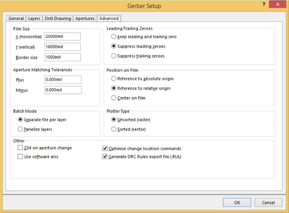
Parameters in Film Size can be set as default by Altium Designer and error may be caused if these parameters
are set to be too small. Parameters in Aperture Matching Tolerances, both Plus and Minus should be set to be
0.005mil.
In Batch Mode item, Separate file per layer should be selected.
Leading/Trailing Zeroes, Position on Film and Plotter Type should be selected based on PCB design engineers'
preference and demands of specific projects. Leading/Trailing Zeroes and Position on Film determined in Gerber
Files should be compatible with that in NC Drill Files.
Among selections in Other item, it is suggested that Optimize change location commands and Generate DRC
Rules export file (.RUL) be ticked while the
other two selections not.
After all the
parameters have been determined, press OK button to complete Gerber file generation.
Mentor Graphics -PADS
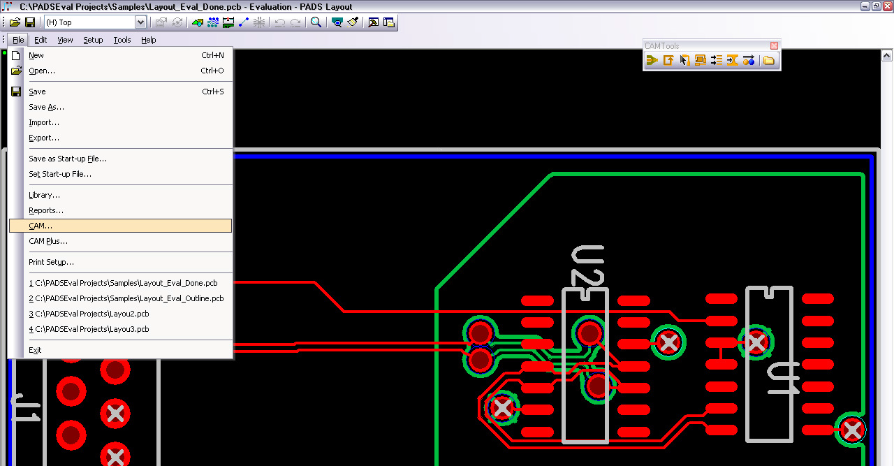
With the .pcb opened in PADs Software, Go to File > CAM
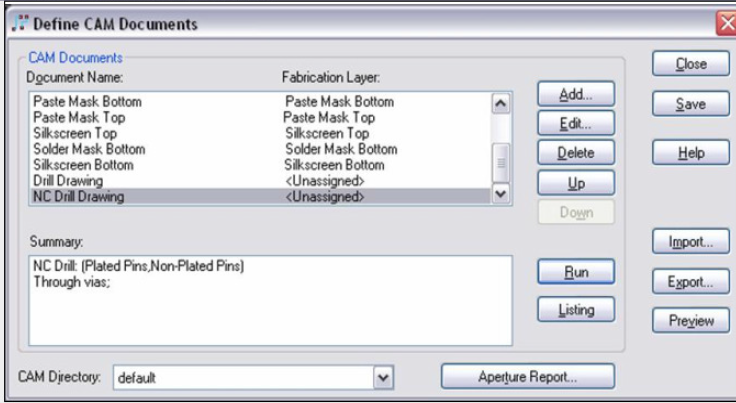
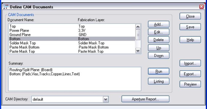
The ‘Define CAM Documents’ window will open and here you can click on the various CAM documents to choose
to generate for your project. Choose ‘Run’ to generate the files.
To generate the NC Drill only, from the same window (Define CAM Documents) Choose ‘NC Drill Drawing’…
Summary will describe the selections for the current document chosen. For instance,
when you choose NC Drill Drawing, the holes and vias will be described in the Summary section. ~ Choose Run
to generate the drill file.
